
The radio receives the broadcast FM band from 88 to 108 MHz. As seen on the front panel, the tuner has a slide-rule dial indicating frequency and a log scale. The only controls are an on/off slide switch below the dial and a tuning knob to the left of the dial.The tuner is quite small measuring 9 5/8 in. wide, 5 7/8 in. deep, and 3 3/4 in. high.
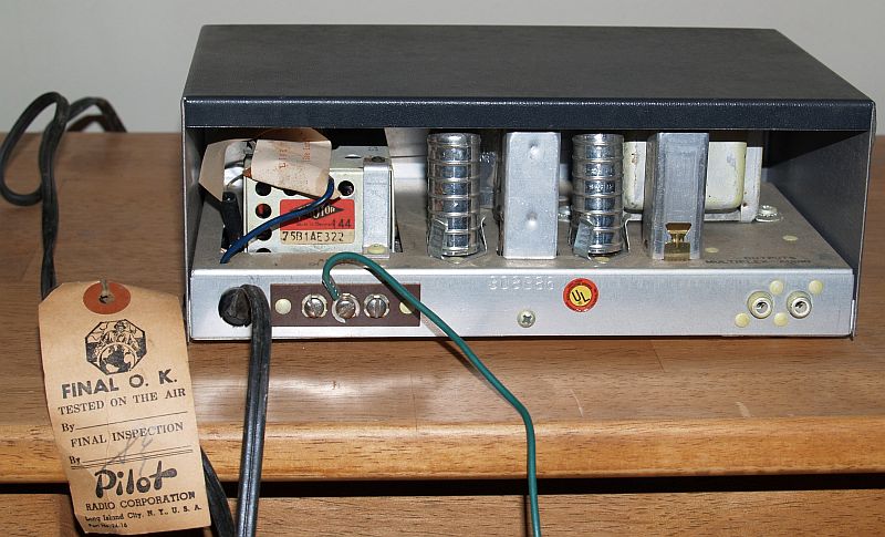
The picture below shows the rear of the tuner. There are two audio outputs on the rear of the tuner. One is a monophonic audio output and the other is for connection to a stereo demultiplexer. Note the power cord still has the factory inspection tag still attached. The three screw terminals on the left are for ground and antenna connections. The green wire attached to one screw is a long wire acting as an antenna. The wire stuffed inside the tuner on the left can be connected to the antenna terminal board to use the line cord as an antenna.
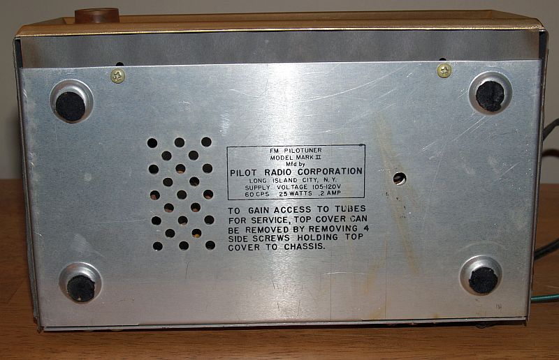
The bottom of the tuner is shown below.
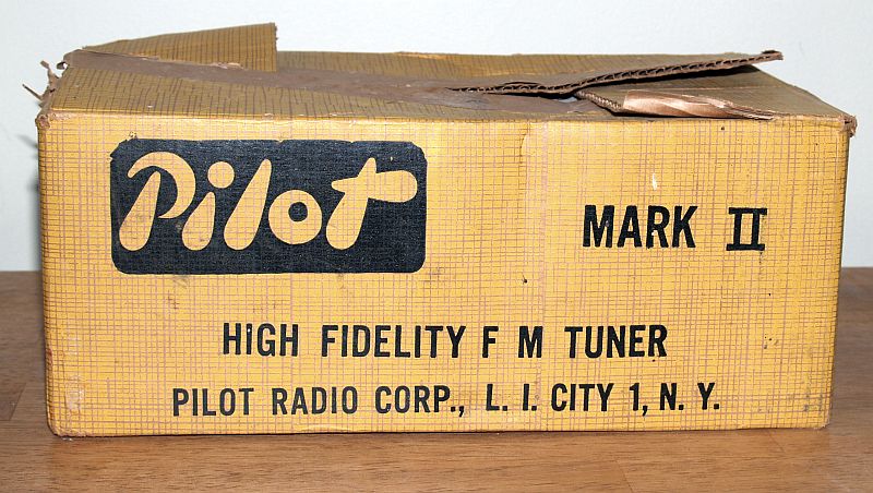
When I acquired the tuner, it had its original box as seen in the picture below.
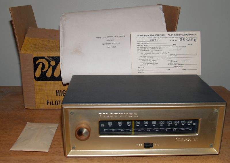
The box still has the inserts to keep the tuner tightly packaged inside the box, waranty card, operating instruction manual with electrical schematic, and chassis mounting screws and washer package for mounting the tuner in a custom cabinet. The manual also included a template for drilling holes to mount the tuner in a cabinet. The picture below shows the tuner, its box, and contents.
I powered up the tuner slowly using a variable transformer. The tuner worked and sounded good in mono as heard through one of my stereo systems.
As previosuly stated, the tuner has four vacuum tubes. One tube functions as an RF amplifier, local oscillator, and mixer. Two tubes comprise the first and second IF amplifiers. One tube is a full wave rectifier. The FM discriminator is a ratio detector comprising two 1N542 diodes inside the detector transformer. According the electrical schematic, the tuner design was approved on 8-27-60.